Fiber Optics Installer
Data connectivity with high-speed and reliable transmission over long distances
Course Overview
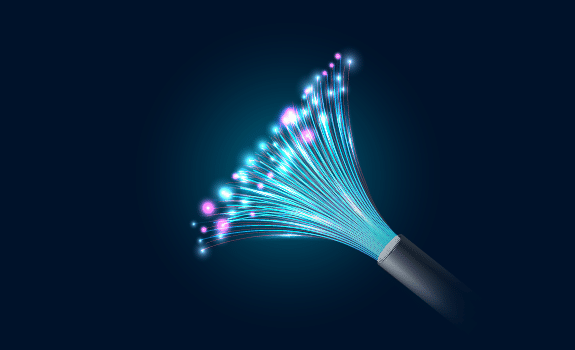
This Fiber Optics Installer training provides fundamental principles, technologies, and practical aspects of fiber optics. It comprises 30% theory and 70% hands-on activities, suitable for beginners, technicians, IT personnel, engineers, and anyone interested in understanding fiber optic technology across various applications.
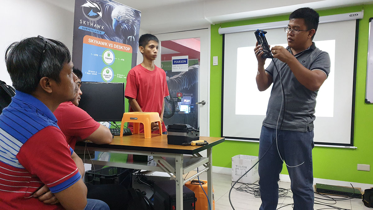
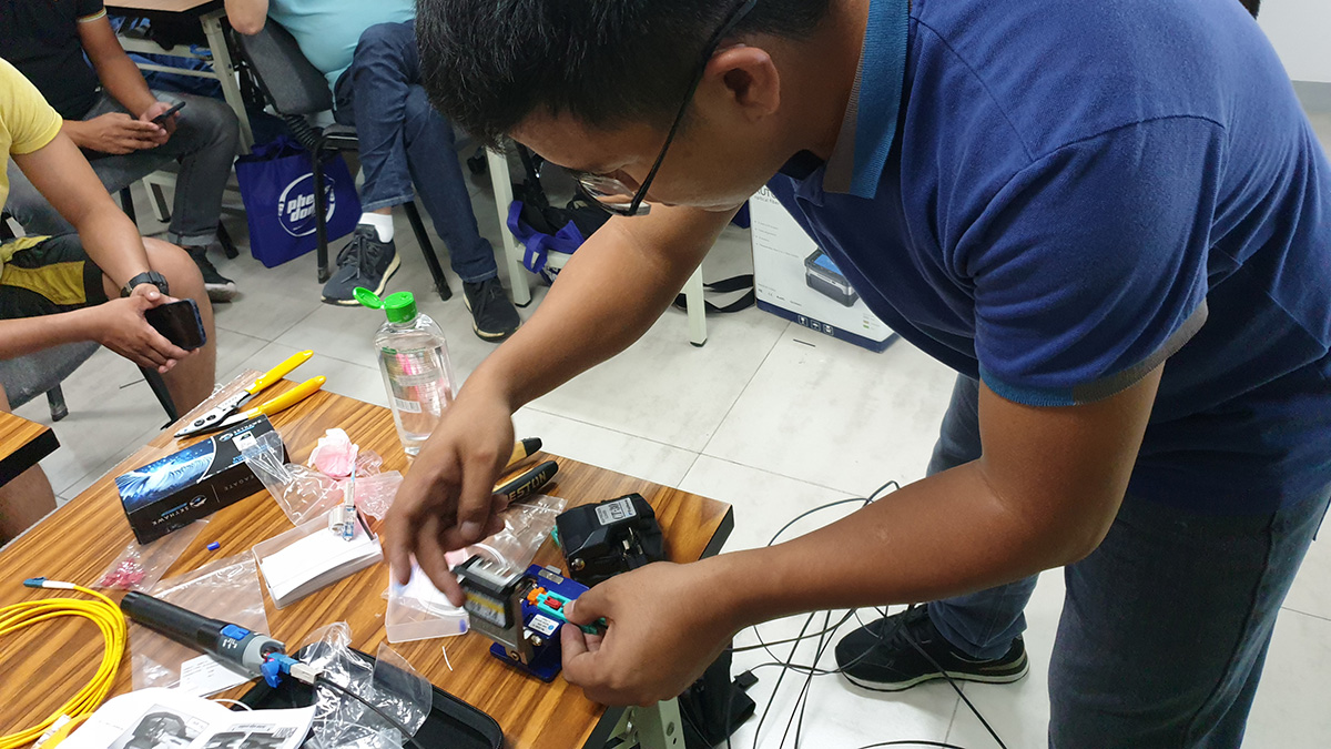
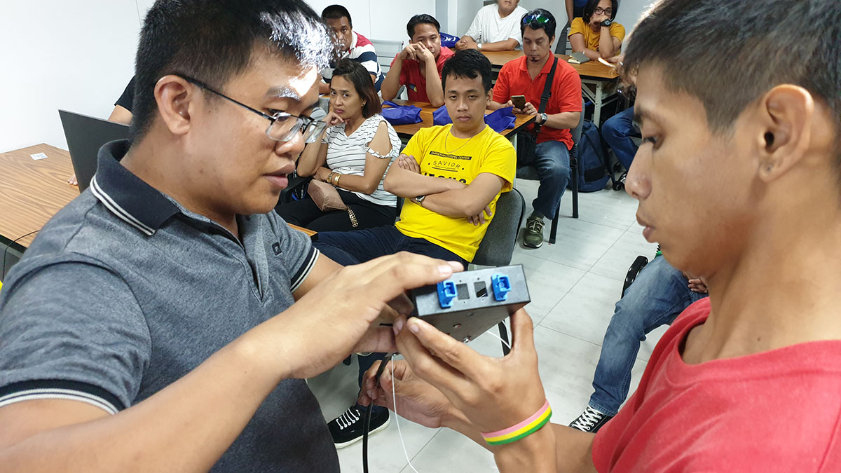
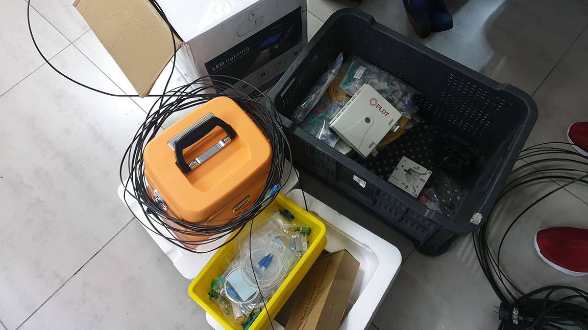
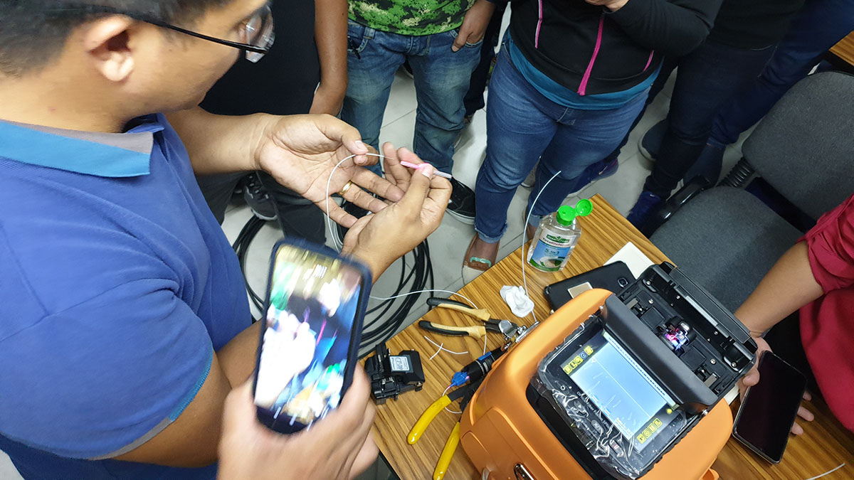
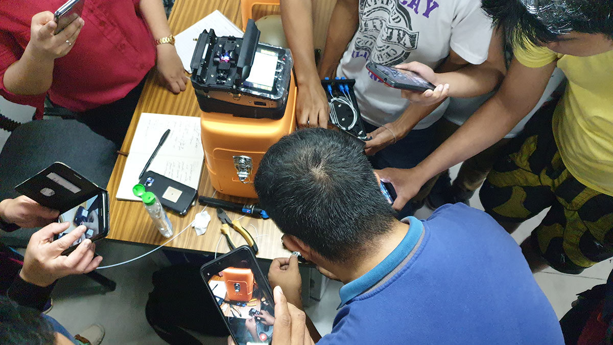
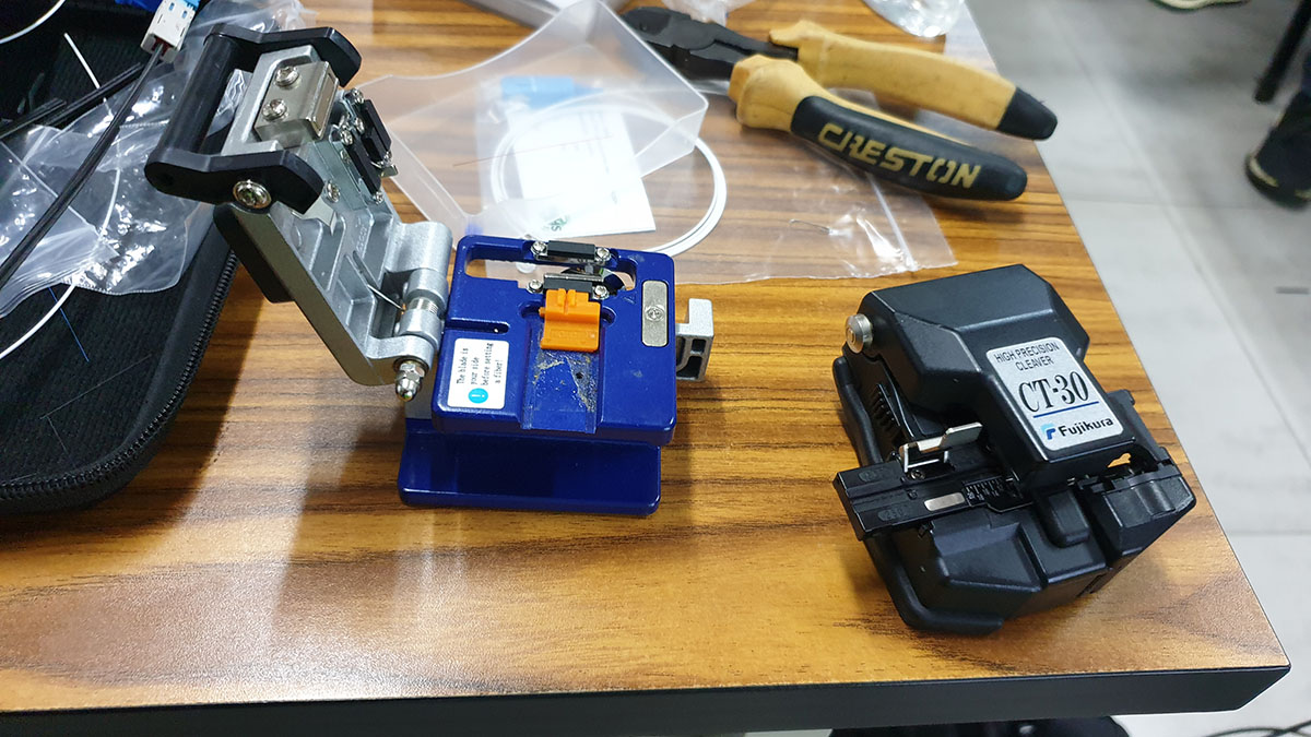
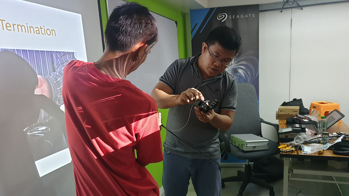
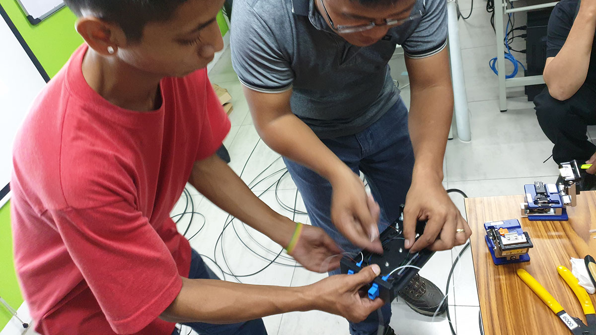
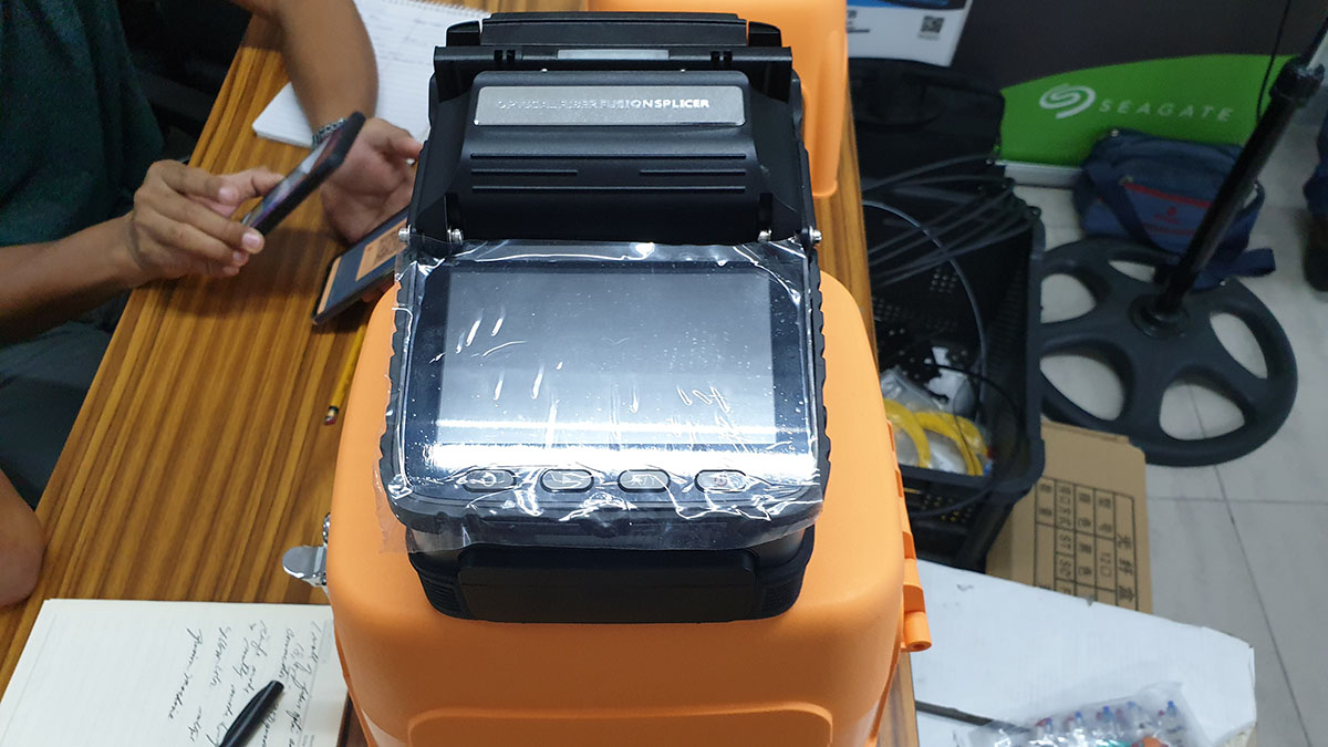
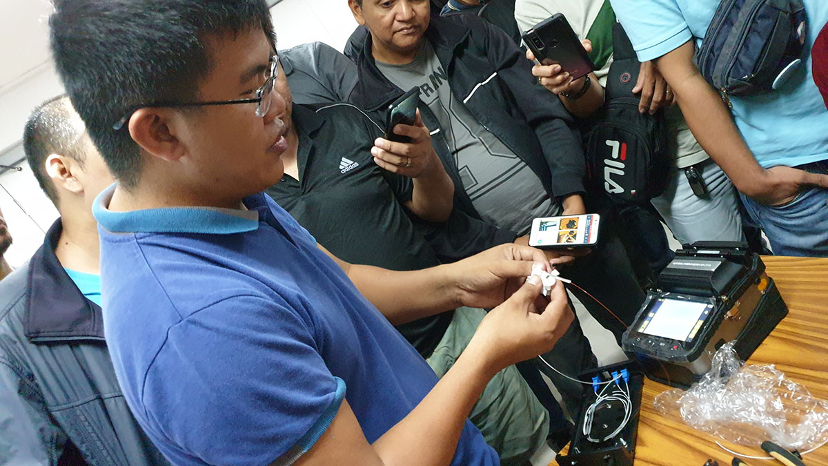
Only International-Grade CCTV and FDAS Training School in the Philippines!
- The first School to offer CCTV Training in the Philippines since 2006
- The only school with an International Grade CCTV and FDAS Facility
- The only school in the Philippines with an Internationally Certified CCTV Trainer (BTEC Certified)
- The only Filipino trainer offering CCTV courses abroad (China, Hong Kong, and Singapore)
- Pearson Vue Accredited Testing Partner
- PhilGEPS Accredited Center
- Globally Recognized Course Certificate
- We’re the top choice for government agencies, LGUs, toll plazas, multinational corporations, universities, security firms, contractors and system integrators.
Frequently Asked Questions
- Basic Computer knowledge and Skills in PC or Mac.
- Basic knowledge in computer hardware and software
- Should be proficient in Networking Essentials both Wired and Wireless
- Certificate of course completion
- Training references (PDF)
- Exercise materials
- Some add-ons
- Free trainer consultation
- Unlimited Free Retakes
Unlimited Retakes = Unlimited Hours of Learning!
We understand that individuals have different learning styles and paces, that’s why we offer the opportunity to learn at your own speed. If you need more time to grasp a concept, you are welcome to come back and retake the class at no additional cost. We believe in providing students with the support they need to succeed.
To Avail: Finish the course to qualify for the unlimited refresher classes
Validity: 1 Year
Course Outline
Day 1
- Overview and History
- History of Light in Communication
- Timeline and Summary of Events
- Key People
- What is Fiber Optics Technology?
- Fiber Optic Manufacturing
- Application of Fiber Optics
- Fiber Optics in Modern Days
- Relevance of Fiber Optics
- Fiber Optic Terminologies
2.0 Fiber Optics Transmission Principle
- Fiber Optics Link
- Parts and Diagram
- Fiber Optics Transmitter and Receiver: Usage and Operation
- Optical Power using decibel milliwatts (dBm)
- Watt to dBm Formula
- Example Computation
- Gain and Loss Explanation using decibel (dB)
- dB as ratio of two power levels
- dB Formula
- Example of dB Computation
3.0 Basic Principles of Light
- Light as Electromagnetic Energy, Particles, and Waves
- Electromagnetic Wave Principle
- Light Propagation
- Light as Charge Particles (Photon)
- Explanation of Electromagnetic Spectrum
- What is Frequency and Wavelength?
- Parts of Electromagnetic Spectrum
- Communication Frequencies (Radio and Microwave)
- Characteristics of Light
- Light Reflection and Refraction
- What is Medium and Index of Refraction?
- Snell’s Law: Formula and Calculation
- Angle of Incidence
- Critical Angle
- Angle of Refraction
- Total Internal Reflection
- Fresnel Reflection: Performance Impact to Fiber Optic Communication
4.0 Fiber Optics Structure, Components, Construction and Theory
- Basic Structure of Fiber Optics
- Core
- Cladding
- Coating
- Standard Organization who governs and define Fiber Optics performance in Telecommunication Industry
- ANSI / TIA
- ISO
- IEC
- ITU-T
- Optical Fiber Material and Tensile Strength
- Fiber Optics Type of Modes
- Single Mode and Multimode
- Effect of Core Diameter and Wavelength
- Refractive Index Profiles
- Single Mode Fiber Propagation
- Multimode Step Index Propagation
- Multimode Graded Index Propagation
- Single Mode and Multimode Bend Insensitive Fiber
- Optical Trench
- Advantages of Bend Insensitive Fiber
5.0 Fiber Optics Characteristics
- Fiber Optic Dispersion
- What is Fiber Optic Dispersion?
- Modal Dispersion
- Modal Dispersion in Multimode
- Effect of Modal Dispersion on the Bandwidth
- Polarization Mode Dispersion
- Polarization Mode Dispersion in Single Mode
- Effect of Polarization Mode Dispersion on the Bandwidth
- Waveguide Dispersion
- Waveguide Dispersion in Single Mode
- Effect of Waveguide Dispersion on the Bandwidth
- Material Dispersion
- Material Dispersion in Single Mode and Multimode
- Effect of Material Dispersion on the Bandwidth
- Chromatic Dispersion
- Chromatic Dispersion in Single Mode and Multimode
- Effect of Chromatic Dispersion on the Bandwidth
- Fiber Optic Attenuation
- Causes of Attenuation
- Attenuation and Wavelength
- Scattering Loss
- Absorption Loss
- Bending Loss
- Types of Bending Losses
- Microbend
- Macrobend
- Bend-Sensitive and Bend-Insensitive Fibers
- Effect on Single Mode
- Effect on Multimode
- ISO/IEC 11801: Fiber Optic Category / Designation
- OS1, OS2
- OM1, OM2, OM3, OM4, OM5 (New)
- IEC 60793-2-10, IEC 60793-2-50: Fiber Optic Category / Designation
- IEC 60793-2-50: B-657.A, B-652.D
- IEC 60793-2-10: A1-OM1 (A1b), A1-OM2 (A1a.1), A1-OM3 (A1a.2), A1-OM4 (A1a.3), A1-OM5 (A1a.4)
- ITU: Fiber Optic Category / Designation
- 657 ,G.652.D
- 651.1
- ANSI/TIA-568, TIA-492-AAA: Fiber Optic Category / Designation
- TIA 492CAAA (OS1), TIA 492CAAB (OS2)
- TIA 492AAAA (OM1), TIA 492AAAB (OM2), TIA 492AAAC (OM3), TIA 492AAAD (OM4), TIA 492AAE (OM5)
- Explain Performance Characteristics of Fiber Optics based on ANSI/TIA-568 and ISO/IEC 11801
- Table of Attenuation vs Distance (Maximum)
- Table of Attenuation vs Distance (Concluded)
- Explain Performance Characteristics of Fiber Optics based on ITU-T G.652, G.655, and G.657
- Table of G.652 (A,B,C,D) Fibre Attributes
- Table of G.655 (C,D,E) Fibre Attributes
- Table of G.657 (A, B) Fibre Attributes
- Explain Performance Characteristics of Other Fiber Optics
- Attenuation and Bandwidth of Hard Clad Silica / Plastic Clad Silica
- Attenuation and Bandwidth of Plastic Optical Fibers
- Causes of Attenuation
6.0 Fiber Optics Safety
- Government agency enforces regulations on safety in the workplace
- Philippine Government Agency: Department of Labor and Employment according to OSHS
- How to safely handle and dispose fiber optic cable and bare fiber optic
- Laser Safety; Do not look at the end of the fiber
- Always test the fiber to check if power is present
- Wear personal protective equipment such as eye protection / laser safety glasses
- Use adhesive tape or specialized waste containers for fiber debris
- Isolate and put in a bag then labeled Fiber Waste
- Laser Hazard Classifications of Fiber Optic Light Source
- Class 1 / Class 1M
- Eye: Safe
- Skin: Safe
- Class 2 / Class 2M
- Eye: Safe for unintentional exposure less than 1/4 second. Do not stare into beam.
- Skin: Safe
- Class 3R
- Eye: Unintentional or accidental exposure to direct or reflected beam has a low risk. Avoid intentional exposure to direct or reflected beam.
- Skin: Safe
- Class 3B
- Eye: Eye hazard; avoid exposure to direct or reflected beam.
- Skin: Can heat skin if beam is held long enough on skin at close range
- Class 4
- Eye: Severe eye hazard; avoid exposure to direct or reflected beam.
- Skin: Can instantly burn skin. Avoid direct exposure to the beam.
- Potential Chemical Hazard and Material Safety Datasheet (MSDS or SDS)
- Epoxy or Curing Agents can release fumes or vapors that may harmful when inhaled. Prolonged or repeated exposure to these chemicals without proper ventilation can lead to respiratory issues, skin irritation, and other health complications
- Adhering to material safety data sheet (MSDS or SDS) guidelines for each chemical can mitigate many of these potential hazards
- Class 1 / Class 1M
Day 2
7.0 Fiber Optics Cable
- Parts of Fiber Optics Cable
- Loose Buffer & Tight Buffer
- Outer Jacket
- Strength Member
- Importance of Each Part
- Gel Filled and Gel Free Loose Buffer Fibre Optic Cables
- Difference of Gel Filled and Gel Free
- Advantages and Disadvantages of Gel Filled
- Advantages and Disadvantages of Gel Free
- Strength Member
- Types of Strength Member
- Differences of Strength Member
- Cordage and Cables
- Difference between Cordage and Cable
- Types of Cordage
- Simplex
- Duplex
- Characteristics of Different Cables
- Distribution Cable
- Breakout Cable
- Armored Cable
- Messenger Cable
- Ribbon Cable
- Submarine Cable
- Hybrid Cable
- Composite Cable
- Fan-Out and Break-Out Kit
- Difference between Fan-Out and Break-Out Kit
- Furcation Tubing
- Manifold / Bullet / Shrink Tube
- Usage and Importance of Fan-Out Kit
- Usage and Importance of Break-Out Kit
- Difference between Fan-Out and Break-Out Kit
- National Electric Code (NEC) Fiber Optics Cable Types
- OFNP – Optical Fiber Nonconductive Plenum Cable
- OFNR – Optical Fiber Nonconductive Riser Cable
- OFNG / OFN – Optical Fiber Nonconductive General Purpose Cable
- NEC Listed and Unlisted Cables
- Listed Cables – ONFP, ONFR, OFNG / OFN
- Unlisted Cables – Outside Cable and Other Unverified / Tested Cable
- Jacket Markings
- Manufacturer Identification, Date of Manufacture, Serial Number
- NEC Listed Cable Marking (Jacket Rating)
- UL Certification
- Fibre Type and Fibre Count
- Fibre Core and Cladding Size
- Cable Diameter
- Cable Distance Marking
- TIA 598 Color Coding
- Show Table of Individual Fiber Color Code (1 to 48)
- Show Table of Indoor Cable Jacket Color Code
8.0 Fiber Optic Splicing
- Intrinsic and Extrinsic Factors
- What is Intrinsic Factor?
- Types of Intrinsic Factor: NA Mismatch, Core Diameter Mismatch, MFD Mismatch, Cladding Diameter Mismatch, Concentricity
- What is Extrinsic Factor?
- Types of Extrinsic Factor: Lateral Misalignment, Air Gap, Angular Misalignment
- Mechanical Splicing
- What is Mechanical Splicing?
- How to assemble mechanical splice?
- Low loss interconnection using mechanical splice
- Fusion Splicing
- What is Fusion Splicing?
- Fusion Splicer Operation
- Low loss interconnection using fusion splice
- Fusion Splicing Alignment Method
- Fixed V-Groove
- Active Cladding Alignment (Movable V-Groove, Cladding Edge Detection)
- Active Core Alignment (Movable V-Groove, Core Location)
- How to protect fusion splice
- ANSI/TIA 568 – Inside Plant Splice Performance Requirement
- Maximum Optical Insertion Loss of 0.3 dB
- Minimum Return Loss of 20 dB for Multimode
- Minimum Return Loss of 35 dB for Single Mode
- ANSI/TIA-758, Telcordia GR-20 – Outside Plant Splice Performance Requirement
- Shall not exceed mean Optical Insertion Loss of 0.1 dB (0.3 dB maximum)
- Shall have a Return Loss greater than or equal to 45 dB mean (40 dB minimum) for Single Mode
9.0 Connectors
- Fiber Optic Connector
- Basic Part of Fiber Optic Connector
- Ferrule
- Connector Body
- Coupling Mechanism
- Ferrule Materials
- Ceramic (Zirconia)
- Polymer Composite Material
- Endface Polish and Geometries
- Flat – Flat surface connection. There’s a small gap between two ferrules when mated.
- Curved – Spherical surface connection. Reduces the air gap to create better contact between two ferrules when mated.
- Angled – Spherical surface connection but angled at 8 degrees based on industry standard. Allows for even tighter connection.
- Lensed –
- Endface Geometry Parameters: Telcordia GR-326
- Define Radius of Curvature
- Define Apex O`set
- Define Fiber Height (Undercut or Protrusion)
- Show summary table for Geometry Parameters based on polish type
- Interferometer
- What is Interferometer?
- How interferometer is used to determine endface geometry
- Insertion Loss and Return Loss
- What is Insertion Loss?
- What is Return Loss?
- Contact and Non-Contact Connector
- Contact Connector – Connectors that have physical contact together
- Example of Contact Connector – LC, SC, ST, FC, E2000
- Non-Contact Connector – New category of connector that doesn’t require any physical contact between two connector or ferrule
- ANSI/TIA-568 Connectors
- 568SC Type Connector
- Array Connectors (MPO)
- Small Form Factor Connector (MT-RJ, LC)
- What is Small Form Factor Connector?
- What is Array Connector (MPO)?
- Oven Cured Epoxy Connector Termination
- Cable and Fiber Preparation (Cable Stripping, Accessories Insertion)
- Epoxy – Ferrule Preparation, Insertion and Oven Curing
- Connector Assembly – Crimping
- Machine Polishing and Endface Inspection
- Anaerobic Epoxy Connector Termination
- Cable and Fiber Preparation (Cable Stripping, Accessories Insertion)
- Pre-assembled connector – Anaerobic Epoxy (Fill up Ferrule with Anaerobic Epoxy)
- Fiber Insertion to Pre-assembled connector (Room Temp Curing)
- Hand Polish and Endface Inspection
- Machine Polish vs Hand Polish
- Advantage and Disadvantages
- Endface Appearance Consistency
- Pre-Polished Connector Termination
- Field Installable Connectors
- Pre-Polish Fiber inside the connector body
- Strip, Cleave, Insert the Fiber to Pre-Polish Connector
- Wet-Cleaning and Dry-Cleaning
- Dry-Cleaning Techniques
- Inspect the endface
- Use a lint – free wipes
- Wipe the connector endface in one direction
- Inspect the endface
- Wet-Cleaning Techniques
- Inspect the endface
- Use a lint – free wipes
- Apply a drop of solvent in lint – free wipes
- Wipe the connector endface in one direction
- Inspect the endface
- Better Technique – Combination of Wet to Dry Cleaning
- Dry-Cleaning Techniques
- Show a summary table of endface connector inspection criteria based on ANSI/TIA-455-57 and IEC 61300-3-35
- ANSI/TIA-568: Maximum Insertion Loss and Return Loss for Mated Pairs
- Insertion Loss: SM and MM 0.75 dB
- Return Loss: SM 35 dB, 55dB for CATV then MM 20 dB
- ITU-T G.671: Maximum Insertion Loss and Return Loss for Single Mode Single Fiber Mated Connector Pairs
- Insertion Loss: SM 0.5 dB
- Reflectance (Return Loss): SM 35 dB
- ANSI/TIA-568 Color Code for Multimode and Single Mode Connectors
- and Adapters
- Single Mode – OS1, OS2: Blue
- Single Mode – OS1, OS2 Angled Connector: Green
- OM3 / OM4 – Aqua
- OM2 – Black
- OM1 – Beige
- Basic Part of Fiber Optic Connector
10.0 Fiber Optics Light Sources
- LED Light Sources
- Basic Operation
- Low Power Output
- Large light beam output
- Types of LED light sources
- Surface-Emitting LED
- Edge-Emitting LED
- Injection Laser Diode
- Performance Characteristics
- Monochromatic
- Lower Power Consumption
- Shock Resistant
- Well-Suited for Multimode Fiber Links
- Laser Light Sources
- Basic Operation
- High Power Output
- Smaller light beam output
- Types of Laser light sources
- VCSEL – Vertical-Cavity Surface-Emitting Laser
- FP – Fabry Perot
- DFB – Distributed Feedback Lasers
- EML – Electro-absorption Modulated Laser
- Performance Characteristics
- Power Stability
- Narrow Spectral Output
- Well-Suited for Single Mode Fiber Links
- LED Transmitter vs Laser Transmitter
- Difference of the LED and Laser Transmitter
- Basic Operation
- Basic Operation
LED Transmitters are used mainly in short to moderate transmission while Laser Transmitter are mainly used over long distances
- Serial Laser Transmitter
- The sequential transmission of signal elements of a data group. The characters are transmitted in a sequence over a single fiber, rather than simultaneously over two or more fibers, as in parallel transmission.
- Parallel Laser Transmitter
- The simultaneous transmission of related signal elements over two or more separate fibers. Parallel optics relies on spatial division multiplexing, in which a signal is spatially divided among multiple fibers and simultaneously transmitted across those fibers.
11.0 Fiber Optic Detectors and Receivers
- Photodiode
- What is Photodiode?
- Basic Operation of Photodiode
Converts photons (light) into electrical current
- Fiber Optic Receiver
- What is Fiber Optic Receiver?
- Component
- Photodiode
- Transimpedance Amplifier
- Data recovery circuit
- Dynamic Range and Operating Wavelength
- Dynamic Range – difference between the minimum and maximum signal that you can put through a link for a given traffic bandwidth
- Operating Wavelength – specific range of wavelengths that are utilized for communication purposes
- Explain Importance of Optical Attenuator
- Optical Attenuators are passive devices that reduce the strength of signals traveling through fiber optic cables. It used to mitigate signal loss, thereby maintaining signal integrity and allowing for extended reach in optical networks. attenuators are crucial in applications where fine-tuning or enhancing signal quality is important, including long-distance communication systems
Day 3
12.0 Fiber Optic Cable Installation and Hardware
- Manufacturer Installation Cable Specification
- Show and Explain the Table of ANSI/TIA-568 Performance Specification for Fiber Optic Cables – Premises Cabling Standards
- Inside Plant cable: Single Mode, 1 dB/km Attenuation
- Indoor-Outdoor Cable: Single Mode, 0.5 dB / km Attenuation
- Outside Plant Cable: Single Mode, 0.4 dB / km Attentuation
- Drop Cable
- Show and Explain the Table of ANSI/TIA-568 Static and Dynamic Load on Fiber Optic cable during installation
- Inside Plant cable: 220N (2 or 4 Fibres)
- Indoor-Outdoor Cable: 1335N (up to 12 Fibres) 2670N (more than 12 Fibres)
- Outside Plant Cable: 2670N
- Drop Cable: 440N
- Fiber Optic Hardware: Description
- Patch Panel
- Racks and Cable
- Splice Enclosure
- Types of Installation: Description
- Tray and Duct
- Conduit
- Direct Burial
- Aerial
- Blown Fiber
- Wall Plate
- Permitted Locations bases on NEC Article 770. Show Table in 770.154
- Plenum – Ducts, Environmental Air, Plenums, Vertical Run, General Purpose
- Riser – Vertical Run, General Purpose
- General Purpose – General Purpose
- Unlisted OSP – General Purpose and does not exceed 15m from the point of entrance
13.0 Fiber Optic System Advantages
- Show Bandwidth Advantage over Twisted Pair and Coaxial Copper Cables
- Show Attenuation Advantage over Twisted Pair and Coaxial Copper Cables
- Explain electromagnetic immunity over Copper Cables
- Describe and show size advantages of fiber optic over copper cable
- Describe and show weight advantages of fiber optic over copper cable
- Describe and show security advantages of fiber optic over copper cable
- Describe and show safety advantages of fiber optic over copper cable
14.0 Fiber Optic Test Link/Cable Testing
- Explain importance of test equipment calibration
- Types of Fiber Optic Test Equipment for Continuity Checking
- Visible Fault Locator (VFL)
- Optical Loss Test Set (OLTS) (OLS and OPM)
- Explain Visible Fault Locator Operation
- Explain single mode and multimode Optical Loss Test Set Operation
- Explain what is patch cord (jumper)?
- Explain what is measurement quality jumper (master jumper)
- What is a Mode Filter?
- Explain Mandrel Wrap and its usage according to ANSI/TIA-526-14-A
- Describe and explain how to measure optical loss in patch cord using steps in ANSI/TIA-526-14
- Method A – Two Jumper Reference
- Method B – One Jumper Reference
- Tier 1 Testing – OLTS
- Equipment Needed
- Explain the Parameters
- Operation: How to Setup and Read Result
- Tier 2 Testing – OTDR
- Equipment Needed
- Explain the Parameters
- Operation: How to Setup and Read Graph (Result)
Premium Experience
- Fully Air-Conditioned Training Rooms
- Complete Set of Fiber Optic Equipment
- Fiber Optic Switches and Media Converters
- Workstation for Every Student
- Free Coffee & Fast WiFi
- Lifetime Access to Online Consultations
- Unlimited FREE Class Retakes
Single Course Discount
april 2025
may 2025
About the Registration
Feel free to register! Registering does not commit you to paying for the course immediately. Registration helps us track attendee numbers and enables us to stay in touch. Payment will only be requested once the course is confirmed to proceed.
Note: When choosing a schedule, you are limited to the available training dates posted on our website.